-
January 22nd, 2011, 07:46 PM
#1
Senior Hostboard Member

Re: Crossover Help Needed With ANOTHER Pair of ALTECS
Well if there was ever an endorsement for recapping crossover networks, I don't remember a better one. Glad it all worked out so well for you.
Yeah GM, the Hakko stations are pretty good, I use a 936 with brass tip cleaner and have totally weaned myself from the wet sponge. I concentrate on board work so the adjustability is not often used, but it sure comes in handy when working with point-to-point stuff. I am eyeing up the Hakko 808 desoldering tool, now. Reports are that it is akin to sliced bread. 
On a totally off topic note,GM....... I have finally received into inventory, six new sheets of Baltic Birch ply for the stalled "MLTL Large Model 19" we discussed back in forgotten history. I have the original thread bookmarked and will bring it back to life when I have some birch sawdust on the floor. FWIW, I returned the previous Birch ply that I had, there were quality concerns. For new material, I visited my local hardwoods supplier and was able to select my own sheets out of a birch packing crate that had some indeciferable (maybe Latvian?) script on the crate.
-
January 22nd, 2011, 11:28 PM
#2
Senior Hostboard Member

Re: Crossover Help Needed With ANOTHER Pair of ALTECS
I recapped both Model 14's today. As much as I'd like to say it was another huge success, unfortunately I hit a "snag" and I need to ask the experts out there a question. I started out just like I did with the Model 19's. I set the two Model 14's up one right next to the other and did an A/B listening test to verify that they still sound identical just like they did when I bought them. They do still sound identical. I then recapped the crossover in speaker number one. Here's a photo of the successfully recapped crossover.
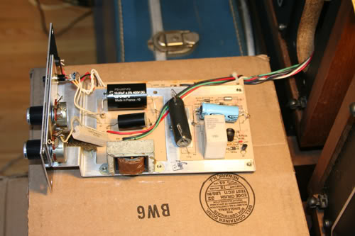
Everything was going great and then I hit a "snag". As I mentioned earlier in this thread, unlike the Model 19's, the caps in the Model 14 crossovers are soldered directly to the circuit board of the crossover. I'm not comfortable soldering directly to a circuit board, so as I mentioned earlier in this thread my plan was to clip the leads from the old caps while being sure to leave enough of the old leads intact and attached to the board to allow me to just solder the new caps to them (solder the leads of the new caps to the portion of the old leads I leave intact/attached to the board). You may now be able to guess what the snag was. This process went great for every connection in this crossover but one. I got nice, secure connections from the new lead of each new cap to the portion of the old leads that I left intact/attached to the board, EXCEPT FOR ONE! While soldering in the 2 uF cap, one of the old leads got loosened/removed from the board by the heat of the soldering process. I had no choice but to solder this one lead directly to the board. So, I poked the lead from the new 2 uF cap through the same hole where the lead from the old 2 uF cap pokes through from the other side, flipped the board over and soldered the new 2 uF lead securely to the board just like the old 2 uF lead was. It went well, I breathed a sigh of relief and now had all three new capacitors soldered securely into the crossover. I put the crossover back into the cabinet and did another A/B comparison. The recapped Model 14 now sounded noticeably better than the one with original caps--similar improvement to what I described in my post earlier today regarding the improvement I noticed in my Model 19's after recapping them. I immediately noticed clearer, cleaner, more detailed sound and improved high frequency characteristics--the high end now appears to roll of at a higher frequency...... Substantial improvement in the treble and midrange sound--not sure if the bass is improved. I'll listen to them as a pair to be sure of that......
OK, here's the part where I need to ask a question of the experts out there. I then started recapping crossover number two. Every solder connection went smoothly except the same old 2 uF capacitor lead on this crossover got loosened/detached during the soldering process as happened in crossover #1. So, I had to solder this 2 uF lead directly to the board just like I did in crossover #1. While soldering this lead directly to the board, I accidentally fed a little too much solder to the connection and caused a big drop of solder to form on the board. Unfortunately, this "big drop" of solder touches the solder connection directly below it as well. If you look at the two photos below, the first one shows where I soldered the one 2 uF capacitor lead directly to the circuit board. In the top center of the photo, there are 3 solder connections right next to each other, each one right below the next (three in a vertical row). There is no big drop of solder connecting the top two solder connections (the top one is where the 2 uF lead is attached). In the next photo, you can see where I soldered the one 2 uF lead directly to the board and accidentally dripped a "big drop" of solder that connects the top two out of three solder connections (and possibly the third as well although I think that the second and third were already connected by solder on this crossover). Sorry the first photo is a little dark--I didn't realize the flash didn't go off due to my work light being on.
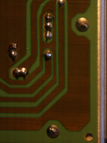
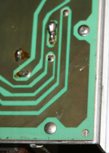
Anyways, here's my question for the experts. After examining the circuit board in both speaker crossovers, I noticed that some of the solder connections that are very close to each other/right next to each other are either on the verge of touching or appear to be actually touching due to the amount of solder used. Other solder connections on the boards are far apart from each other and are not touching or on the verge of touching any other solder connections. For example, on the left side of both photos you can see where two "separate" solder connections (that I haven't touched) that are right next two each other are clearly connected to each other by the amount of solder used. My hypotheses is that the solder connections that are extremely close to each other on the board are actually connected to each other at some point so it's OK if the solder touches or is on the verge of touching these connections together whereas the solder connections that are isolated must remain isolated and must not touch anything else. Is this theory correct and therefore is it OK that the "big drop" of solder is connecting 2 out of the 3 solder connections (or 3 out of the 3)? If not, I'll have to try to "melt off" the big drop of solder and I'd really like to avoid having to do any more soldering directly to this board other than the one connection I've already done. I'm not going to hook this speaker up to my amp for fear of potentially causing damage until I hear from the experts out there that it is OK for the connections that are that close on this board to touch due to the amount of solder used because they are connected anyways. The recapping process went great on both Model 14's and I have nice, secure solder connections for all of the new capacitors -- the only snag is that I need to know is if this "big drop" is a problem. The 2 uF cap is securely soldered in place but I'm not sure if the connection that the "big drop" causes to the next solder connection is a problem. I'm trying to not beat myself up too much considering all four Model 19 recaps and both Model 14 recaps went great/all nice secure solder connections and the only potential snag is this one "big drop". However, it's hard to not beat myself up about this when I'm afraid to hook up my Model 14's to my amp because of this "big drop" of solder....... Thanks in advance to anyone who can shed light on this question---in the meantime my Model 14's are out of commission:doh:
-
January 23rd, 2011, 08:11 AM
#3
Senior Hostboard Member

Re: Crossover Help Needed With ANOTHER Pair of ALTECS
You need to buy ( & then learn to operate ) a solder sucker ;
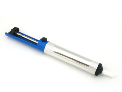
- I typically use a solder sucker to clean up a pc boards' ( pads/holes ) before inserting the leads of any new components .
- FWIW, in practise, I use a solder sucker 5 times more often than desoldering braid ( which you should also own ) .
Here's a good ( step by step ) article on desoldering ( found by Googling "solder sucker ) . Click the following logo ;

- BTW, I agree with the authors advice about using only a 25 to 30 watt iron when working on PC boards ( like what is displayed ) .
- Crossover boards are a bit different in that the traces are typically much larger/thicker & more robust .
cheers <> EarlK
ps ; Glad your new caps are working out for you .
-
January 23rd, 2011, 11:05 AM
#4
Senior Hostboard Member
Re: Crossover Help Needed With ANOTHER Pair of ALTECS
Thanks for the info Earl--I'll read the article this afternoon. I still need to know -- can I leave that big drop of solder where it is in the meantime? Is it OK for those two (or 3) connections that are right next to each other to touch? Are connections that are that close to each other on this board/grouped together, connected at some point anyways? I'm guessing that if they weren't connected at some point they wouldn't be grouped together so closely--there are plenty of other connections on the board that have more space between them and those three look purposely "grouped together" (as do the two connections to their left in both photos that are grouped together and are also touching due to the amount of solder used when the boards were originally assembled). My Model 14's are out of commission until I get an answer to this question as I'm afraid to hook up my amp to that speaker until I hear that it's safe to do so with that big drop of solder connecting two (or three) of the solder connections......
-
January 23rd, 2011, 01:14 PM
#5
Senior Hostboard Member

Re: Crossover Help Needed With ANOTHER Pair of ALTECS

Originally Posted by
voice of the theater

...........I still need to know -- can I leave that big drop of solder where it is in the meantime? ..............
...............My Model 14's are out of commission until I get an answer to this question as I'm afraid to hook up my amp to that speaker until I hear that it's safe to do so with that big drop of solder connecting two (or three) of the solder connections......
Hi VOTT,
I just saw your post.........and compared both the pictures posted by you.
As the pictures were a bit dark, I also processed them so that no wrong conclusions are there.
Yes you can leave the soldering as it is.
It is one and the same (common) joint electrically for all the individual 3 of them.
Generally speaking, close-knit joints like these mostly belong to a common point, but this may not be always true. But in this case it is a common joint and you can happily power up & commission your Model 14's......enjoy 
Aditya
-
January 23rd, 2011, 02:21 PM
#6
Senior Hostboard Member
Re: Crossover Help Needed With ANOTHER Pair of ALTECS
Aditya--thank you so much for your answer to my question--you just made my day! I was ecstatic that the recap for all four Model 19 crossovers went so well--all solder connections nice and neat and secure and a substantial improvement in the sound of all four Model 19's. Likewise, every solder connection in the Model 14 crossovers were nice, neat, and secure except the one connection in question where a drop of solder dripped--it was a secure connection but that connection was not neat. I had a feeling that those three connections shared a common joint and that it was actually not a problem but as I mentioned I didn't want to power up that particular Model 14 until I got a definite answer. The first recapped Model 14 sounded so great that I can't wait to now power up the second one and hopefully verify that it has also received a substantial upgrade in sound quality. I'll do some listening today and tomorrow and hopefully post some good news soon! Thanks again to everyone here for all the help on upgrading the 19's and 14's crossovers.....
-
January 23rd, 2011, 02:47 PM
#7
HB Super Moderator


Re: Crossover Help Needed With ANOTHER Pair of ALTECS
Hey VOT, It's really nice to see you making so much progress !! Keep up the great work ! :2thumbsup:
-
January 26th, 2011, 04:46 AM
#8
Senior Hostboard Member
Re: Crossover Help Needed With ANOTHER Pair of ALTECS
Originally Posted by
voice of the theater
Aditya--thank you so much for your answer to my question--you just made my day! I was ecstatic that the recap for all four Model 19 crossovers went so well--all solder connections nice and neat and secure and a substantial improvement in the sound of all four Model 19's. Likewise, every solder connection in the Model 14 crossovers were nice, neat, and secure except the one connection in question where a drop of solder dripped--it was a secure connection but that connection was not neat. I had a feeling that those three connections shared a common joint and that it was actually not a problem but as I mentioned I didn't want to power up that particular Model 14 until I got a definite answer. The first recapped Model 14 sounded so great that I can't wait to now power up the second one and hopefully verify that it has also received a substantial upgrade in sound quality. I'll do some listening today and tomorrow and hopefully post some good news soon! Thanks again to everyone here for all the help on upgrading the 19's and 14's crossovers.....
It looks from the pictures that the soldering has gone well for you. Congrats!
Since you've chosen to solder to the leads, it appears that the Solen caps are now suspended above the circuit board. It might behoove you to use some Blue-tac or even silicone to attach the caps onto the boards. There is a thing called microphonics, also, that attachment to the board will alleviate.
 Posting Permissions
- You may not post new threads
- You may not post replies
- You may not post attachments
- You may not edit your posts
-
Forum Rules
This forum has been viewed: 28236960 times.



Bookmarks